Rover system on a Jetson Nano Dev Kit
Last update: 2022-06-29
Table of Content
Operating System#
Installation#
You can select one of below method:
Pre-built image#
-
Download the latest Jetson Nano Developer Kit SD Card Image. Other older versions can be found in Jetpack Archive.
As the pre-built image is about 13 GB, which includes full JetPack source, libraies and example, you will need a micro-SD Card with at least 32 GB to be able to install ROS.
-
Download balenaEtcher and install it, and write Jetson Image in an SD Card.
-
Power on the board, either use Monitor with Keyboard and Mouse, or use Headless Mode by using DC jack (Jumper J48 connected) and connect micro-USB port to PC.
Headless setup only available on the virtual COM port when power up via DC Jack!
UART2 @ J50Starting kernel ... [ 0.000000] earlycon: uart8250 at MMIO32 0x0000000070006000 (options '') [ 0.000000] bootconsole [uart8250] enabled [ 15.823522] Please complete system configuration setup on the serial port provided device mode connection. e.g. /dev/ttyACMx where x can 0, 1, 2 etc.
Build an official image#
To not include the Jetpack source code, libraries and example, you can follow the guide in Build system image to create a new system image which is about 5.5 GB. This image will have full OS and pre-installed software, such as Office, Web Browser, etc.
Power on the board, either use Monitor with Keyboard and Mouse, or use Headless Mode by using DC jack (Jumper J48 connected) and connect micro-USB port to PC.
Build a customized image#
To create a lightweight system image, checkout jetson-custom-image and follow the scripting steps to make a customized image. Note to run extra steps in the folder custom_bsp_for_nano_dev_kit.
The final image is about 2.4 GB, which only includes Ubuntu base, lightweight Xfce desktop environment, Jetson driver and libraries, and some BSP modifications
- Skip handling key pressing during U-Boot:
- Disable
bootdelayin U-Boot by settingCONFIG_BOOTDELAY=-2 - Keep one boot entry in
extlinux.conf
- Disable
- Add
spidevto/etc/modulesto load SPI driver at startup - Add user to
tty,dialout,gpiogroups - Enable Autologin
- Run on-screen keyboard
onboardat start-up
There is no setup process required anymore. Use a keyboard and mouse to start working on the board. For touchable monitor, use onboard program to access to on-screen keyboard.
System config#
General#
- Time Mode:
UTC - Username:
jetson - Password:
cccc - APP Partition Size:
0(max size) - Primary Network:
dummythen skip network setting (will add USB WiFi later) - Hostname:
rover - Nvpmodel:
MAXNMaximum power scheme
After finishing system configuration, system console are available at:
- Physical UART1 at
/dev/ttyTHS1run by a service - Physical UART2 at
/dev/ttyS0started by command line option - Virtual COM Port at
/dev/ttyGS0run when micro-USB is connected in device mode
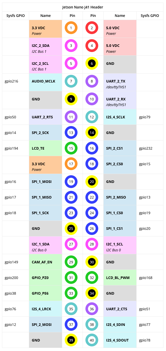
UART ports
Jetson Nano has 3 physical UART ports:
- UART0 at the M2 Slot for WiFi/BT card
- UART1 at the J41 Header (40-pin connector) for System Console after boot up (run by a service), Pin 8 - TX, Pin 10 - RX
- UART2 at the J50 header for debug (early access during boot from bootloader), Pin 4 - RX, Pin 5 - TX
Network#
WiFi is used for main communication with host PC, as the Ethernet port is used to connect to Lidar.
Plug TP-Link WN725N USB dongle, make sure it is recognized.
lsusb
Bus 001 Device 004: ID 0bda:8179 Realtek Semiconductor Corp. RTL8188EUS 802.11n Wireless Network Adapter
Then Wireless interface also appears and is ready to check:
sudo ifconfig wlan0 up
List WiFi Network:
sudo iwlist wlan0 scan
sudo nmcli device wifi list - List info on your wifi signal
Connect to an AP:
sudo nmcli device wifi connect "SSID" password "PASSWORD"
SSH connection
With network enabled, through either Ethernet or WiFi, Jetson board will be also accessed via SSH. If using any X11-forwarding SSH client, such as MobaXterm, GUI app can be show through SSH.
In some case, it is recommended to turn power saving mode off
sudo iw dev wlan0 set power_save off
Update the system at the first time:
sudo apt update
Ethernet should be set to use a static IP which is in the subnet of 192.168.1.0 where Lidar is also set its IP in.
Bring up the interface:
sudo ifconfig eth0 up
Edit the network interface:
auto eth0
iface eth0 inet static
    address 192.168.1.12
    netmask 255.255.255.0
It is needed to change network connection priority, as Linux prefers to use Ethernet when it is connected.
Install ifmetric tool:
sudo apt install -y ifmetric
To use this, first see the metrics using route command:
route -n
Kernel IP routing table
Destination     Gateway         Genmask         Flags Metric Ref    Use Iface
0.0.0.0         10.42.0.1       0.0.0.0         UG    100    0        0 eth0
0.0.0.0         10.42.0.2       0.0.0.0         UG    600    0        0 wlan0
Here, eth0 has lower metric, so it will be preferred over wlan0. If you want to prefer wlan0, then lower its metric:
sudo ifmetric wlan0 50
Now Linux will be using wlan0 for Internet. The change will be reflected immediately.
Tweaks#
To skip entering password on sudo command, add current user to sudoers with the rule NOPASSWD:
sudo bash -c "echo '$USER ALL=(ALL) NOPASSWD: ALL' > /etc/sudoers.d/$USER"
Install nano for editing in terminal:
sudo apt update && \
sudo apt install -y nano
To make terminal display colorfully, in .bashrc, enable force_color_prompt=yes.
To disable animation on GUI:
gsettings set org.gnome.desktop.interface enable-animations false
Enable SPI#
Starting from L4T kernel 32.4.2+, the initial user created in system configuration will be added into all GPIO groups. Run groups to see the current user is added into gpio, i2c. Note that, Jetson L4T does not have spi group, SPI devices use gpio group.
By default, GPIO and I2C are enabled. SPI, PWM, I2S and some extra pins are disabled.
To change the setting of GPIO, the official tool jetson-io.py will be used:
sudo /opt/nvidia/jetson-io/jetson-io.py
This tool will configure the Device Tree and add it using FDT option in the /boot/extlinux/extlinux.conf file
In Jetpack 4.6, SPI device driver are not loaded into kernel, a manual method is to run sudo modprobe spidev, but spidev should be added into /etc/modules to load that driver at boot time.
sudo bash -c 'echo spidev > /etc/modules'
UART Config#
UART1#
The stock Jetson Nano starts a console on the /dev/ttyTHS1 serial port at startup through a service /etc/systemd/nvgetty.sh which launches getty. Note that normal udev rules will be overridden by the console while the service is running.
To disable the console:
sudo systemctl stop nvgetty && \
sudo systemctl disable nvgetty && \
sudo udevadm trigger
UART2#
The debug serial interface is chosen at the startup of kernel. From L4T kernel 32.4.2+, the debug serial can be disabled through the command line options.
The command line can be read from /proc/cmdline:
cat /proc/cmdline
append: tegraid=21.1.2.0.0 ddr_die=4096M@2048M section=512M memtype=0 vpr_resize usb_port_owner_info=0 lane_owner_info=0 emc_max_dvfs=0 touch_id=0@63 video=tegrafb no_console_suspend=1 console=ttyS0,115200n8 debug_uartport=lsport,4 earlyprintk=uart8250-32bit,0x70006000 maxcpus=4 usbcore.old_scheme_first=1 lp0_vec=0x1000@0xff780000 core_edp_mv=1075 core_edp_ma=4000 gpt earlycon=uart8250,mmio32,0x70006000 root=/dev/mmcblk0p1 rw rootwait rootfstype=ext4 console=ttyS0,115200n8 console=tty0 fbcon=map:0 net.ifnames=0 quiet root=/dev/mmcblk0p1 rw rootwait rootfstype=ext4 console=ttyS0,115200n8 console=tty0 fbcon=map:0 net.ifnames=0
Examine /boot/extlinux/extlinux.conf:
TIMEOUT 30
DEFAULT primary

MENU TITLE L4T boot options

LABEL primary
      MENU LABEL primary kernel
      LINUX /boot/Image
      INITRD /boot/initrd
      APPEND ${cbootargs} quiet root=/dev/mmcblk0p1 rw rootwait rootfstype=ext4 console=ttyS0,115200n8 console=tty0 fbcon=map:0 net.ifnames=0
Even it is impossible to edit ${cbootargs} without rebuilding kernel, it is still possible to set new command line by overriding the APPEND field.
Remove ttyS0
Take the expanded command line in /proc/cmdline and remove all console=ttyS0,115200n8 options, make a new value for APPEND.
When a cmdline’s console= is set, the auto-generated serial-getty@ttyXy.service should start agetty and provide system console on that device. If there is no console= option presented, system will attempt to open the first virtual serial port at /dev/tty0.
Reboot the system. Check the dmesg log to see 3 UART ports are available, and system console is on tty0:
dmesg | grep tty
[    0.001665] console [tty0] enabled
[    1.591294] 70006000.serial: ttyS0 at MMIO 0x70006000 (irq = 63, base_baud = 25500000) is a Tegra
[    1.592156] 70006040.serial: ttyTHS1 at MMIO 0x70006040 (irq = 64, base_baud = 0) is a TEGRA_UART
[    1.592584] 70006200.serial: ttyTHS2 at MMIO 0x70006200 (irq = 65, base_baud = 0) is a TEGRA_UART
UART2 still is accessible in boot up time, as it is attached to the bootloader. Send any data at very early time will stop the auto boot. To fix this point, need to use a modifided Uboot firmware.
After reboot, run below command to check if there is any ttyS0 or ttyTHSx is running. It should not show any of them.
ps -aux | grep tty
Permission#
To get rid of using sudo permission, add current user into the dialout and spi group.
Run ls -al /dev/tty* to check the user group of ttyS0, ttyTHS1. Normally, it is needed to add current user into tty and dialout groups. For SPI, it is under gpio group:
sudo usermod -a -G tty,dialout,gpio $USER && \
sudo reboot
UART Testing
For testing, a serial terminal must be installed. Choose one of below.
putty
sudo apt install -y putty
putty
Follow GUI to run.
minicom
sudo apt install -y minicom
minicom -D /dev/ttyS0 -b 115200
Press Ctrl-A X to exit.
picocom
sudo apt install -y picocom
picocom /dev/ttyS0 -b 115200
Press Ctrl-A and Ctrl-X to exit.
screen
sudo apt install -y screen
screen /dev/ttyS0 115200
Press Ctrl-A K to exit.
Wiring#
Refer to below pinout diagram:

UART RX/TX problem
Here is some reports showing that Jetson boards have problems on UART RX/TX pin when connecting that port directly to an other board. It maily causes by the capitive loading on the pin, if the loop-back test does not have any problem.
If that problem happens, please add a 10K pull-down resister on RX/TX pin.
Refer to Unreliable serial communcation via the UART TX/RX GPIO Pins.
Serial driver#
Download source code and build:
git clone https://github.com/vuquangtrong/SerialPort.git && \
cd SerialPort && \
make && \
sudo make install
An example to communicate with Serial port:
// Serial library
#include "serial/SerialPort.h"
#include <unistd.h>
#include <stdio.h>

#define SERIAL_PORT "/dev/ttyS0"

int main( /*int argc, char *argv[]*/) {
    SerialPort serial;

    char errorOpening = serial.openDevice(SERIAL_PORT, 115200);
    if (errorOpening!=1) return errorOpening;
    printf ("Successful connection to %s\n",SERIAL_PORT);

    // Display ASCII characters (from 32 to 128)
    for (int c=32;c<128;c++)
    {
        serial.writeChar(c);
        usleep(10000);
    }

    // Read lines and print them out
    char line[1024];

    while(1) {
        int n = serial.readBytes(line, sizeof(line));
        if (n>=0) {
            std::cout << std::string(line, n) << std::endl;
        }
    }

    // Close the serial device
    serial.closeDevice();

    return 0 ;
}
Compile and run:
g++ example.cpp -lserial -o example
nRF24L01p driver#
Download source code from GitHub and build:
git clone https://github.com/vuquangtrong/RF24 && \
cd RF24 && \
./configure --driver=SPIDEV && \
make && \
sudo make install
Work with the original source code
GitHub source code is at https://github.com/nRF24/RF24.
The guide to install in Linux at https://nrf24.github.io/RF24/md_docs_linux_install.html.
Download the install.sh file:
wget http://tmrh20.github.io/RF24Installer/RPi/install.sh
Make it executable:
chmod +x install.sh
Run it and choose the option:
- RF24 Core
- SPIDEV driver
./install.sh
Do you want to install GIT using APT (Used to download source code) [y/N]? n
Do you want to install the RF24 core library, [y/N]? y
Do you want to install the RF24Network library [y/N]? n
Do you want to install the RF24Mesh library [y/N]? n
Do you want to install the RF24Gateway library [y/N]? n

Cloning into './rf24libs/RF24'...

__* Install RF24 core using? *__
1.BCM2835 Driver(Performance) 2.SPIDEV(Compatibility, Default)
3.WiringPi(Its WiringPi!) 4.MRAA(Intel Devices) 5.LittleWire
2
...
[Installing Libs to /usr/local/lib]
[Installing Headers to /usr/local/include/RF24]
Fix CS pin
Jetson Nano spi-tegra114 driver has an issue in driving the CSN pin, therefore, the SPI command must explicitly request to toggle CSN pin.
Open the file ~/rf24libs/RF24/utility/SPIDEV/spi.cpp to find tr.cs_change = 0; and replace them by tr.cs_change = 1;.
Go back to the `~/rf24libs/RF24 and rebuild the library:
sudo make clean all install
Fixed in a Seeed Studio’s branch, but not in Nvidia’s
Refer: spi: tegra: handle cs_change in modes sw_based_cs & cs_gpios.
Source to test data receiving. Check the transferring site in Base.
#include <iostream>    // cin, cout, endl
#include <time.h>      // CLOCK_MONOTONIC_RAW, timespec, clock_gettime()
#include <RF24/RF24.h>

// create RF24 instance
RF24 radio(15 /* CE = sys_gpio_15 */,
            0 /* CSN = 0 means spidev0.0 */
            /* default speed is 10 Mbps */);

// max payload of RF24 is 32 bytes
uint8_t payload[32];
uint32_t total_nrx = 0;

// custom defined timer for evaluating transmission time in microseconds
struct timespec startTimer, endTimer;

int main(int argc, char** argv) {
    setbuf(stdout, NULL);

    // perform hardware check
    if (!radio.begin()) {
        cout << "radio hardware is not responding!!" << endl;
        return 0; // quit now
    }

    radio.setPayloadSize(32);
    radio.setChannel(100); // 2400 + 100 = 2500 MHz, out of WiFi band

    // address, defaut length is 5
    uint8_t rx_address[6] = "1Addr"; // read from
    radio.openReadingPipe(1, rx_address); // using pip 1

    // (smaller) function that prints raw register values
    radio.printDetails();
    // (larger) function that prints human readable data
    radio.printPrettyDetails();

    // Start
    std::cout << "Start RX" << std::endl;
    radio.startListening(); // put radio in RX mode

    uint8_t pipe;
    uint8_t nrx;

    clock_gettime(CLOCK_MONOTONIC_RAW, &startTimer); // start the timer
    cout << "Begin: " << startTimer.tv_sec << "." << startTimer.tv_nsec << endl;
    while(true) {
        if(radio.available(&pipe)) {
            nrx = radio.getPayloadSize();
            radio.read(&payload, nrx);
            total_nrx += nrx;

            if (total_nrx >= 1000000) {
            clock_gettime(CLOCK_MONOTONIC_RAW, &endTimer); // end the timer
            cout << "End: " << endTimer.tv_sec << "." << endTimer.tv_nsec << endl;
            break;
            }
        }
    }

    int32_t diff_sec = endTimer.tv_sec - startTimer.tv_sec;
    int32_t diff_nsec = endTimer.tv_nsec - startTimer.tv_nsec;
    if (diff_nsec < 0) {
        diff_nsec = 1000000000 - diff_nsec;
        diff_sec -= 1;
    }

    cout << "Received 1000000 bytes in " << diff_sec << "." << diff_nsec << " seconds" << endl;
}
Compile the source code:
g++ -Ofast -Wall -pthread rf24_rx.cpp -lrf24 -o rf24_rx
Run it and see the log:
================ SPI Configuration ================
CSN Pin         = /dev/spidev0.0
CE Pin          = Custom GPIO15
SPI Speedz      = 10 Mhz
================ NRF Configuration ================
STATUS          = 0x0e RX_DR=0 TX_DS=0 MAX_RT=0 RX_P_NO=7 TX_FULL=0
RX_ADDR_P0-1    = 0x65646f4e31 0x7264644131
RX_ADDR_P2-5    = 0xc3 0xc4 0xc5 0xc6
TX_ADDR         = 0x65646f4e31
RX_PW_P0-6      = 0x20 0x20 0x20 0x20 0x20 0x20
EN_AA           = 0x3f
EN_RXADDR       = 0x03
RF_CH           = 0x64
RF_SETUP        = 0x03
CONFIG          = 0x0e
DYNPD/FEATURE   = 0x00 0x00
Data Rate       = 1 MBPS
Model           = nRF24L01+
CRC Length      = 16 bits
PA Power        = PA_LOW
ARC             = 0
================ SPI Configuration ================
CSN Pin                 = /dev/spidev0.0
CE Pin                  = Custom GPIO15
SPI Frequency           = 10 Mhz
================ NRF Configuration ================
Channel                 = 100 (~ 2500 MHz)
RF Data Rate            = 1 MBPS
RF Power Amplifier      = PA_LOW
RF Low Noise Amplifier  = Enabled
CRC Length              = 16 bits
Address Length          = 5 bytes
Static Payload Length   = 32 bytes
Auto Retry Delay        = 1500 microseconds
Auto Retry Attempts     = 15 maximum
Packets lost on
    current channel     = 0
Retry attempts made for
    last transmission   = 0
Multicast               = Disabled
Custom ACK Payload      = Disabled
Dynamic Payloads        = Disabled
Auto Acknowledgment     = Enabled
Primary Mode            = TX
TX address              = 0x65646f4e31
pipe 0 ( open ) bound   = 0x65646f4e31
pipe 1 ( open ) bound   = 0x7264644131
pipe 2 (closed) bound   = 0xc3
pipe 3 (closed) bound   = 0xc4
pipe 4 (closed) bound   = 0xc5
pipe 5 (closed) bound   = 0xc6
Start RX
Begin: 793.156527770
End: 821.645141301
Received 1000000 bytes in 28.488613531 seconds
The example receives 1 MB in 28.5 seconds, which means 35 KBps. While the transfer rate set on the channel is 1Mbps (equals 125 KBps), the example only achieve 28% of bandwidth.
OLED driver#
Download source code and build:
git clone https://github.com/vuquangtrong/OLED_SSD1306_I2C_Linux.git && \
cd OLED_SSD1306_I2C_Linux && \
make && \
sudo make install
Write a simple app to a progress bar with label and numeric value:
#include <string.h>
#include <unistd.h>
#include <SSD1306/ssd1306.h>

int main() {
    char counter = 0;
    char buffer[3];
    SSD1306_Init("/dev/i2c-1");
    while(1) {
        sprintf(buffer, "%d", counter++);
        SSD1306_Clear();
        SSD1306_WriteString(0,0, "counter:", &Font_7x10, SSD1306_WHITE, SSD1306_OVERRIDE);
        SSD1306_WriteString(0,10, buffer, &Font_11x18, SSD1306_WHITE, SSD1306_OVERRIDE);
        SSD1306_DrawRectangle(0,28,128,4,SSD1306_WHITE);
        SSD1306_DrawFilledRectangle(0,28,counter*128/256,4,SSD1306_WHITE);
        SSD1306_Screen_Update();
        sleep(0.2);
    }
    return 0;
}
Compile and run:
gcc progress_bar.c -lssd1306 -o progress_bar && \
./progress_bar
ROS Melodic#
Adding repository and source list
sudo apt-add-repository universe
sudo apt-add-repository multiverse
sudo apt-add-repository restricted
sudo apt update
Setup source list to get ROS packages:
sudo sh -c 'echo "deb http://packages.ros.org/ros/ubuntu $(lsb_release -sc) main" > /etc/apt/sources.list.d/ros-latest.list'
Add keys:
sudo apt install -y curl && \
curl -s https://raw.githubusercontent.com/ros/rosdistro/master/ros.asc | sudo apt-key add -
Pull the package list:
sudo apt update
Install ROS Melodic desktop:
sudo apt install -y ros-melodic-desktop
It’s convenient if the ROS environment variables are automatically added to a bash session every time a new shell is launched:
echo "source /opt/ros/melodic/setup.bash" >> ~/.bashrc && \
source ~/.bashrc
A good way to check the installation is to ensure that environment variables like ROS_ROOT and ROS_PACKAGE_PATH are set:
printenv | grep ROS
ROS_ETC_DIR=/opt/ros/melodic/etc/ros
ROS_ROOT=/opt/ros/melodic/share/ros
ROS_MASTER_URI=http://localhost:11311
ROS_VERSION=1
ROS_PYTHON_VERSION=2
ROS_PACKAGE_PATH=/opt/ros/melodic/share
ROSLISP_PACKAGE_DIRECTORIES=
ROS_DISTRO=melodic
Initialize the package rosdep to track package dependency:
sudo apt install -y python-rosdep && \
sudo rosdep init && \
rosdep update
Build packages are needed for code compilation.
sudo apt install -y python-rosinstall python-rosinstall-generator python-wstool build-essential
Create a catkin workspace and try to build it:
mkdir -p ~/catkin_ws/src && \
cd ~/catkin_ws/src && \
catkin_init_workspace && \
cd .. && \
catkin_make
The workspace should be built successfully.
Livox SDK#
Dependencies#
Livox SDK needs to be built in the host machine, therefore, some tool-chain and build tools have to be installed.
sudo apt update && \
sudo apt install -y build-essential && \
sudo apt install -y curl && \
sudo apt install -y git && \
sudo apt install -y cmake
The pointcloud Library (PCL) is a large scale, open project[1] for pointcloud processing. The PCL framework contains numerous state-of-the art algorithms including filtering, feature estimation, surface reconstruction, registration, model fitting and segmentation.
sudo apt install -y libpcl-dev
sudo apt install -y ros-melodic-pcl-ros
Eigen is a C++ template library for linear algebra: matrices, vectors, numerical solvers, and related algorithms.
sudo apt install -y libeigen3-dev
OpenCV (Open Source Computer Vision Library) is an open-source computer vision library and has bindings for C++, Python, and Java. It is used for a very wide range of applications, including medical image analysis, stitching street view images, surveillance video, detecting and recognizing faces, tracking moving objects, extracting 3D models, and much more. OpenCV can take advantage of multi-core processing and features GPU acceleration for real-time operation.
sudo apt install -y python-opencv python3-opencv
Re-link libraries, on Jetson Nano:
sudo ln -s /usr/bin/vtk6 /usr/bin/vtk && \
sudo ln -s /usr/lib/python2.7/dist-packages/vtk/libvtkRenderingPythonTkWidgets.aarch64-linux-gnu.so /usr/lib/aarch64-linux-gnu/libvtkRenderingPythonTkWidgets.so
Livox SDK#
The official guide is at https://github.com/Livox-SDK/Livox-SDK.
Livox SDK is the software development kit designed for all Livox products. It is developed based on C/C++ following Livox SDK Communication Protocol, and provides easy-to-use C style API. With Livox SDK, users can quickly connect to Livox products and receive pointcloud data.
Installation
git clone https://github.com/Livox-SDK/Livox-SDK.git && \
cd Livox-SDK && \
cd build && \
cmake .. && \
make && \
sudo make install
The Livox SDK will be built and installed in /usr/local/lib:
Install the project...
-- Install configuration: ""
-- Installing: /usr/local/lib/liblivox_sdk_static.a
-- Installing: /usr/local/include/livox_def.h
-- Installing: /usr/local/include/livox_sdk.h
Livox ROS driver#
Get livox_ros_driver from GitHub
git clone https://github.com/Livox-SDK/livox_ros_driver.git ws_livox/src
Then build it:
cd ws_livox && \
catkin_make
If running catkin_make gives error of command not found, it’s probably that the ROS setup.bash is not executed and included in ~/.bashrc. See above section to source it.
This driver will create a new node named livox_lidar_publisher, which publishes 2 new types of messages:
Livox pointcloud message
# Livox publish pointcloud msg format.

Header header             # ROS standard message header
uint64 timebase           # The time of first point
uint32 point_num          # Total number of pointclouds
uint8  lidar_id           # Lidar device id number
uint8[3]  rsvd            # Reserved use
CustomPoint[] points      # Pointcloud data
Livox Point
# Livox custom pointcloud format.

uint32 offset_time      # offset time relative to the base time
float32 x               # X axis, unit:m
float32 y               # Y axis, unit:m
float32 z               # Z axis, unit:m
uint8 reflectivity      # reflectivity, 0~255
uint8 tag               # livox tag
uint8 line              # laser number in lidar
Configurations#
The configuration file is in ws_livox/src/livox_ros_driver/config.
LiDAR’s configuration parameter
| Parameter | Type | Description | Default |
|---|---|---|---|
broadcast_code |
String | LiDAR broadcast code | N/A |
enable_connect |
Boolean | false | |
return_mode |
Int | Return mode: 0 – First single return mode 1 – The strongest single return mode 2 – Dual return mode |
0 |
coordinate |
Int | Coordinate: 0 – Cartesian 1 – Spherical |
0 |
imu_rate |
Int | Push frequency of IMU sensor data: 0 – stop push 1 – 200 Hz Currently only Horizon supports this, MID serials do not support it |
0 |
extrinsic_parameter_source |
Int | Whether to enable extrinsic parameter automatic compensation of LiDAR external reference 0 – Disabled 1 – Enabled |
0 |
Timestamp synchronization
| Parameter | Type | Description | Default |
|---|---|---|---|
enable_timesync |
Boolean | false | |
device_name |
String | Name of the serial device which outputs GPRMC/GNRMC messages every second | /dev/ttyUSB0 |
comm_device_type |
Int | Type of device sending timestamp information 0 – Serial port or USB virtual serial port device other – not support |
0 |
baudrate_index |
Int | Baud rate of serial device: 0 – 2400 1 – 4800 2 – 9600 3 – 19200 4 – 38400 5 – 57600 6 – 115200 7 – 230400 8 – 460800 9 – 500000 10 – 576000 11 – 921600 |
2 (9600) |
parity_index |
Int | parity type 0 – 8 bits data without parity 1 – 7 bits data 1bit even parity 2 – 7 bits data 1bit odd parity 3 – 7 bits data 1bit 0, without parity |
0 |
{
    "lidar_config": [
        {
            "broadcast_code": "1PQDH5B00100041",
            "enable_connect": false,
            "return_mode": 0,
            "coordinate": 0,
            "imu_rate": 0,
            "extrinsic_parameter_source": 0,
            "enable_high_sensitivity": false
        }
    ],
    "timesync_config": {
        "enable_timesync": false,
        "device_name": "/dev/ttyUSB0",
        "comm_device_type": 0,
        "baudrate_index": 2,
        "parity_index": 0
    }
}
Timestamp#
Prepare a GPS device to ensure that the GPS can output UTC time information in GPRMC/GNRMC format through the serial port or USB virtual serial port, and support PPS signal output.
- Connect the GPS serial port to the host running
livox_ros_driver, set the corresponding device name in the config file - Connect the GPS PPS signal line to LiDAR
- Be sure to set the output frequency of GPRMC/GNRMC time information of GPS to 1 Hz
Launches#
Different launch files have different configuration parameter values and are used in different scenarios:
| Launch file name | Description |
|---|---|
livox_lidar.launch |
Connect to Livox LiDAR device Publish pointcloud2 format data |
livox_lidar_msg.launch |
Connect to Livox LiDAR device Publish livox customized pointcloud data |
livox_lidar_rviz.launch |
Connect to Livox LiDAR device Publish pointcloud2 format data Autoload rviz |
Launch parameters
| Parameter | Description | Default |
|---|---|---|
publish_freq |
Set the frequency of pointcloud publish | 10.0 |
multi_topic |
0 – All LiDAR devices use the same topic to publish pointcloud data 1 – Each LiDAR device has its own topic to publish pointcloud data |
0 |
xfer_format |
0 – Livox pointcloud2(PointXYZRTL) pointcloud format 1 – Livox customized pointcloud format 2 – Standard pointcloud2 (PointXYZI) pointcloud format in the PCL library |
0 |
Test ROS#
An easy method to connect Livox Lidar with Jetson board is through a LAN router. Below section shows another method to connect 2 modules directly.
Set Livox’s Static IP
Use Livox Viewer to set a Static IP for the Lidar module. Livox only accepts IP in 192.168.1.0 network.
Set Jetson’s Static IP
sudo nano /etc/network/interfaces
auto lo
iface lo inet loopback

auto eth0
iface eth0 inet static
        address 192.168.1.12
        netmask 255.255.255.0
Then run the livox_lidar_rviz example
cd ws_livox
source ./devel/setup.bash
roslaunch livox_ros_driver livox_lidar_rviz.launch
This will run Livox ROS and Rviz to visualize the received pointcloud.
Auto-mount USB#
Check out and install:
git clone https://github.com/vuquangtrong/USB_Automount.git && \
cd USB_Automount && \
./install
Plugged-in USB will be mounted into /media/<Label> or /media/<sdXy>.
Automount scripts
Here are scripts to auto-mount storage devices:
sudo nano /usr/local/bin/usb-mount.sh
#!/bin/bash

# This script is called from our systemd unit file to mount or unmount
# a USB drive.

usage()
{
    echo "Usage: $0 {add|remove} device_name (e.g. sdb1)"
    exit 1
}

if [[ $# -ne 2 ]]; then
    usage
fi

ACTION=$1
DEVBASE=$2
DEVICE="/dev/${DEVBASE}"

# See if this drive is already mounted, and if so where
MOUNT_POINT=$(/bin/mount | /bin/grep ${DEVICE} | /usr/bin/awk '{ print $3 }')

do_mount()
{
    if [[ -n ${MOUNT_POINT} ]]; then
        echo "Warning: ${DEVICE} is already mounted at ${MOUNT_POINT}"
        exit 1
    fi

    # Get info for this drive: $ID_FS_LABEL, $ID_FS_UUID, and $ID_FS_TYPE
    eval $(/sbin/blkid -o udev ${DEVICE})

    # Figure out a mount point to use
    LABEL=${ID_FS_LABEL}
    if [[ -z "${LABEL}" ]]; then
        LABEL=${DEVBASE}
    elif /bin/grep -q " /media/${LABEL} " /etc/mtab; then
        # Already in use, make a unique one
        LABEL+="-${DEVBASE}"
    fi
    MOUNT_POINT="/media/${LABEL}"

    echo "Mount point: ${MOUNT_POINT}"

    /bin/mkdir -p ${MOUNT_POINT}

    # Global mount options
    OPTS="rw,relatime"

    # File system type specific mount options
    if [[ ${ID_FS_TYPE} == "vfat" ]]; then
        OPTS+=",users,gid=100,umask=000,shortname=mixed,utf8=1,flush"
    fi

    if ! /bin/mount -o ${OPTS} ${DEVICE} ${MOUNT_POINT}; then
        echo "Error mounting ${DEVICE} (status = $?)"
        /bin/rmdir ${MOUNT_POINT}
        exit 1
    fi

    echo "__** Mounted ${DEVICE} at ${MOUNT_POINT} **__"
}

do_unmount()
{
    if [[ -z ${MOUNT_POINT} ]]; then
        echo "Warning: ${DEVICE} is not mounted"
    else
        /bin/umount -l ${DEVICE}
        echo "____ Unmounted ${DEVICE}"
    fi

    # Delete all empty dirs in /media that aren't being used as mount
    # points. This is kind of overkill, but if the drive was unmounted
    # prior to removal we no longer know its mount point, and we don't
    # want to leave it orphaned...
    for f in /media/* ; do
        if [[ -n $(/usr/bin/find "$f" -maxdepth 0 -type d -empty) ]]; then
            if ! /bin/grep -q " $f " /etc/mtab; then
                echo "____ Removing mount point $f"
                /bin/rmdir "$f"
            fi
        fi
    done
}

case "${ACTION}" in
    add)
        do_mount
        ;;
    remove)
        do_unmount
        ;;
    *)
        usage
        ;;
esac
Change permission:
sudo chmod 0755 /usr/local/bin/usb-mount.sh
Add service:
sudo nano /etc/systemd/system/usb-mount@.service
[Unit]
Description=Mount USB Drive on %i

[Service]
Type=oneshot
RemainAfterExit=true
ExecStart=/usr/local/bin/usb-mount.sh add %i
ExecStop=/usr/local/bin/usb-mount.sh remove %i
The file name uses
@to pass arguments.
Add rules for udev when USB event is detected:
sudo nano /etc/udev/rules.d/99-usb-mount.rules
KERNEL=="sd[a-z][0-9]", SUBSYSTEMS=="usb", ACTION=="add", RUN+="/bin/systemctl start usb-mount@%k.service"
KERNEL=="sd[a-z][0-9]", SUBSYSTEMS=="usb", ACTION=="remove", RUN+="/bin/systemctl stop usb-mount@%k.service"
Restart services and rules:
sudo udevadm control --reload-rules && \
sudo systemctl daemon-reload
If a USB is not mount automatically, check the system log:
cat /var/log/syslog
Auto-start application#
A simple app that shows IP Address on OLED screen.
#include <iostream>
#include <string>
#include <cstring>
#include <sys/socket.h>
#include <netinet/in.h>
#include <arpa/inet.h>
#include <unistd.h>
#include <sys/types.h>
#include <ifaddrs.h>
#include <SSD1306/ssd1306.h>

using namespace std;
char i2c_dev[] = "/dev/i2c-1";
char noIP[] = "No IP";

void showIP(int line, char type, char* ip) {
    char buffer[32] = {0};
    sprintf(buffer, "%c:%s", type, ip);
    SSD1306_WriteString(0,line*10, buffer, &Font_7x10, SSD1306_WHITE, SSD1306_OVERRIDE);
}

void getIPAddresses() {
    struct ifaddrs *interfaces = NULL;
    struct ifaddrs *temp_addr = NULL;
    int success = 0;
    bool found = false;
    // retrieve the current interfaces - returns 0 on success
    success = getifaddrs(&interfaces);
    if (success == 0) {
        // Loop through linked list of interfaces
        temp_addr = interfaces;
        while(temp_addr != NULL) {
            if(temp_addr->ifa_addr->sa_family == AF_INET) {
                // Check if interface is en0 which is the wifi connection on the iPhone
                if(strcmp(temp_addr->ifa_name, "wlan0")==0){
                    showIP(0, 'W',
                        inet_ntoa(((struct sockaddr_in*)temp_addr->ifa_addr)->sin_addr)
                    );
                    found = true;
                }
                if(strcmp(temp_addr->ifa_name, "eth0")==0){
                    showIP(1, 'E',
                        inet_ntoa(((struct sockaddr_in*)temp_addr->ifa_addr)->sin_addr)
                    );
                    found = true;
                }

            }
            temp_addr = temp_addr->ifa_next;
        }
    }
    // Free memory
    freeifaddrs(interfaces);

    if (!found) {
       showIP(3, '?', noIP);
    }
}


int main(int argc, char** argv) {
   SSD1306_Init(i2c_dev);
   while(1) {
      SSD1306_Clear();
      getIPAddresses();
      SSD1306_Screen_Update();
      sleep(10);
   }
}
Create a service:
[Unit]
Description=IP Show
After=multi-user.target

[Service]
Type=simple
ExecStart=/usr/bin/ipshow

[Install]
WantedBy=multi-user.target
Enable the service:
sudo systemctl enable ipshow.service