J-Link SysView - Record and Visualize System Activities
SEGGER's System View (SysView) is a real-time recording and visualization tool for embedded systems that reveals the true runtime behavior of an application, going far deeper than the system insights provided by debuggers. This is particularly effective when developing and working with complex embedded systems comprising multiple threads and interrupts. System View can ensure a system performs as designed, can track down inefficiencies, and find unintended interactions and resource conflicts.
Last update: 2022-06-29
Table of Content
J-Link System View — Manual SEGGER_SysView.zip STM32-Tutorials
System View#
Visit the Official J-Link System View page on SEGGER website for more information.
SEGGER’s J-Link System View is written on top of the excellent J-Link Real-Time Transfer to record many types of events in real-time in an embedded system. Those events can be interrupts, timers, task switches and scheduling within an RTOS, API function calls and returns, or user events and messages. The events are retrieved from the target, analyzed and visualized in the System View Application, while the target keeps running.
System View may be used with a non-commercial license for evaluation, educational and hobbyist purposes. When using System View under the non-commercial license, no activation is required.
How System View works#
To keep the communication overhead on the target system low, it only needs to record basic information, such as Function with ID X is called with parameter values y and z at the n ticks after the last event. System View analyzes all information from the events and shows:
- The recording time or system time when the call happened
- The task/context in which the call happened
- The interrupt name, timer ID, and marker name
- The API function name and its parameters and values
- The duration of the any pair of start-stop, enter-exit events
The timestamps for events can be as accurate as 1 CPU cycle. A regular event is just 4 to 8 bytes long.
What System View helps#
Issues and inefficiencies in the system can be identified below ways:
- Incorrect task priorities or priority inversion leading to starvation
- Incorrect inter-task communication
- Inefficient delays and timeouts
- Spurious or unnecessary interrupts
- Unexpected log run-time of a short task
High CPU Load can lead to:
- Bottlenecks which may lead to delayed execution of important tasks
- Dropped data or overflow of incoming buffer
System View APIs#
The SEGGER System View implementation is written in ANSI C on the top of RTT, therefore, it can be easily integrated into any embedded application. The System View needs to be initialized before it can be used. However, it does not automatically run to reduce CPU Load and power usage. System View only runs when it gets request from Host’s System View Application.
Control functions
| Function | Description |
|---|---|
SEGGER_SYSVIEW_Init() |
Initializes the SYSVIEW module |
SEGGER_SYSVIEW_Start() |
Start recording System View events. This function is triggered by the System View Application on connect. |
SEGGER_SYSVIEW_Stop() |
Stop recording System View events. This function is triggered by the System View Application on disconnect. |
Configuration functions
| Function | Description |
|---|---|
SEGGER_SYSVIEW_Conf() |
Initialize and configures System View |
SEGGER_SYSVIEW_SetRAMBase() |
Sets the RAM base address |
SEGGER_SYSVIEW_SendSysDesc() |
Send the system description string to the host |
SEGGER_SYSVIEW_SendTaskList() |
Send all tasks descriptors to the host |
SEGGER_SYSVIEW_SendTaskInfo() |
Send a Task Info Packet, containing TaskId for identification, task priority and task name |
SEGGER_SYSVIEW_X_GetTimestamp() |
Callback called by System View to get the timestamp in cycles |
Event recording functions
| Function | Description |
|---|---|
SEGGER_SYSVIEW_RecordEnterISR() |
Format and send an ISR entry event |
SEGGER_SYSVIEW_RecordExitISR() |
Format and send an ISR exit event |
SEGGER_SYSVIEW_RecordEnterTimer() |
Format and send a Timer entry event |
SEGGER_SYSVIEW_RecordExitTimer() |
Format and send a Timer exit event |
SEGGER_SYSVIEW_OnIdle() |
Record an Idle event |
SEGGER_SYSVIEW_OnTaskCreate() |
Record a Task Create event |
SEGGER_SYSVIEW_OnTaskStartExec() |
Record a Task Start Execution event |
SEGGER_SYSVIEW_OnTaskStartReady() |
Record a Task Start Ready event |
SEGGER_SYSVIEW_OnTaskStopExec() |
Record a Task Stop Execution event |
SEGGER_SYSVIEW_OnTaskStopReady() |
Record a Task Stop Ready event |
SEGGER_SYSVIEW_OnTaskTerminate() |
Record a Task termination event |
SEGGER_SYSVIEW_MarkStart() |
Record a Performance Marker Start event to start measuring runtime |
SEGGER_SYSVIEW_Mark() |
Record a Performance Marker intermediate event |
SEGGER_SYSVIEW_MarkStop() |
Record a Performance Marker Stop event to stop measuring runtime |
User API recording functions
| Function | Description |
|---|---|
SEGGER_SYSVIEW_RecordVoid() |
Formats and sends a System View packet with an empty payload |
SEGGER_SYSVIEW_RecordU32() |
Formats and sends a System View packet containing a single U32 parameter payload |
SEGGER_SYSVIEW_RecordU32x[2:10]() |
Formats and sends a System View packet containing [2:10] U32 parameter payload |
SEGGER_SYSVIEW_RecordString() |
Formats and sends a System View packet containing a string |
SEGGER_SYSVIEW_RecordEndCall() |
Format and send an End API Call event without return value. |
SEGGER_SYSVIEW_RecordEndCallU32() |
Format and send an End API Call event with a return value |
Message recording functions
| Function | Description |
|---|---|
SEGGER_SYSVIEW_Print() |
Print a string to the host |
SEGGER_SYSVIEW_Warn() |
Print a warning string to the host |
SEGGER_SYSVIEW_Error() |
Print an error string to the host |
SEGGER_SYSVIEW_PrintfHost() |
Print a string which is formatted on the host by the System View Application |
SEGGER_SYSVIEW_WarnfHost() |
Print a string which is formatted on the host by the System View Application |
SEGGER_SYSVIEW_ErrorfHost() |
Print an error string which is formatted on the host by the System View Application |
To reduce CPU cycles used by System View to format strings, System View function *fHost() just sends a raw string and its params to the host!
System View Integration#
Install the System View Application firstly at System View download page.
After installation, go the application folder to get the latest source code of System View target integration, for example C:\Program Files\SEGGER\System View\Src. Here is SEGGER_SysView.zip at version 3.32.
├─Config
│     Global.h                          # Typedef for data types
│     SEGGER_RTT_Conf.h                 # Default RTT configs
│     SEGGER_SYSVIEW_Conf.h             # User SysView Configs
|
├──SEGGER
│  │   SEGGER.h                         # Segger common defines
│  │   SEGGER_RTT.h                     # RTT Header
│  │   SEGGER_RTT.c                     # RTT implementation
│  │   SEGGER_RTT_ASM_ARMv7M.S          # for Cortex-M3/M4
│  │   SEGGER_RTT_printf.c              # Print functions
│  │   SEGGER_SYSVIEW_ConfDefaults.h    # SysView Default Configs
│  │   SEGGER_SYSVIEW_Int.h             # SysView Internal defines
│  │   SEGGER_SYSVIEW.h                 # SysView header
│  │   SEGGER_SYSVIEW.c                 # SysView implementation
│  │
│  └───Syscalls                         # Standard IO redirection
│
└─Sample                                # Sample configs for different targets
  ├───COMM                              # Example to record on UART
  ├───embOS                             #
  ├───FreeRTOSV10                       #
  ├───FreeRTOSV8                        #
  ├───FreeRTOSV9                        #
  ├───MicriumOSKernel                   #
  ├───uCOS-II                           #
  ├───uCOS-III                          #
  └───NoOS                              # Run without OS
     └───Config
         ├───RX
         ├───Cortex-M                   #
         │       SEGGER_SYSVIEW_Config_NoOS.c
         └───Cortex-M0                  # Special setup for Cortex-M0
                 SEGGER_SYSVIEW_Config_NoOS_CM0.c
You can copy all files to your projects and add them to Paths and Symbols settings.
System View with No OS#
This section will guide you on how to add System View into an application and record its activity to analyze them. As System View is based on RTT which runs through SWD interface, the guide to integrate on Cortex-M MCUs is the same in general.
Purpose
- Visualize interruption activity
- Debug the issue of incorrect counter value when pressing on button
Target application
- Blink an LED at 100 Hz using a general Timer
- Increase a counter value by one when press on a Button using External Interrupt
- Send the counter value on an UART port every 100 ms in the main loop
Target platform library
- Use HAL library minimize setup code, and then focus only on System View integration
Target hardware
- STM32 Nucleo-64 F411RE board with Cortex-M4 integration
- STM32 F0-Discovery F051R8 board with Cortex-M0 integration
This guide show steps for F411RE MCU first!
For the case of using F051R8, modification points will be shown in a separated section!
Start a new project#
The selected board is STM32 Nucleo-64 F411RE, refer to steps in Blink example to create a new project using STM32CubeMX.
Here are main settings:
-
USER BUTTON:
Set PC13 to GPIO_EXTI13, with mode
External Interrupt with Falling Edge Trigger Detection, without any Pull-up or Pull-down resistor. -
GREEN LED:
Set PA5 to GPIO_Output, with mode
Push-Pull, without any Pull-up or Pull-down resistor. -
TIMER 10:
Enable TIM10 with Prescaler =
1600and Counter Period =1000 -
USART 2:
Enable USART2 on pin PA2 and PA3, with baudrate =
115200and parameters =8N1. This UART port is connected to ST-LINK Virtual COM port. -
NVIC:
Enable Interrupt for EXTI line[15:10], TIM10 Global, and USART2 Global
The main program:
- Implement TIM10 Update Event callback to toggle the LED
- Implement EXTI13 External Interrupt callback to increase the counter value
- Declare UART TX Complete callback without any code (will be modified later)
- In main, start the TIM10 in Interrupt Mode
- In main loop, print out counter value via UART port
#include "main.h"
#include <stdio.h>
#include <string.h>

//#define USE_UART_INTERRUPT

TIM_HandleTypeDef htim10;
UART_HandleTypeDef huart2;

char counter = 0;
char buffer[16] = {0}; // counter=xxx\r\n

void SystemClock_Config(void);
static void MX_GPIO_Init(void);
static void MX_TIM10_Init(void);
static void MX_USART2_UART_Init(void);

void HAL_TIM_PeriodElapsedCallback(TIM_HandleTypeDef *htim) {
  if(htim == &htim10) {
    HAL_GPIO_TogglePin(LED_GPIO_Port, LED_Pin);
  }
}

void HAL_GPIO_EXTI_Callback(uint16_t GPIO_Pin) {
  if(GPIO_Pin == GPIO_PIN_13) {
    counter++;
  }
}

void HAL_UART_TxCpltCallback(UART_HandleTypeDef *huart) {
  if(huart == &huart2) {
  }
}

int main(void)
{
  HAL_Init();
  SystemClock_Config();
  MX_GPIO_Init();
  MX_TIM10_Init();
  MX_USART2_UART_Init();

  HAL_TIM_Base_Start_IT(&htim10);
  while (1)
  {
    sprintf(buffer, "counter = %03d\r\n", counter);
#ifndef USE_UART_INTERRUPT
    HAL_UART_Transmit(&huart2,
        (uint8_t*)buffer, strlen(buffer), HAL_MAX_DELAY
    );
#else
    HAL_UART_Transmit_IT(&huart2,
        (uint8_t*)buffer, strlen(buffer), HAL_MAX_DELAY
    );
#endif
    HAL_Delay(100);
  }
}
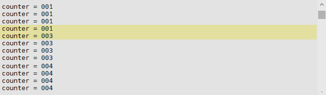
Build and run the application, then press on the User Button, you will notice, sometimes the counter value is increased incorrectly!!!
Import System View files#
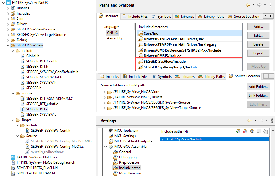
The base files of SEGGER System View can be added in a separated folder, e.g. SEGGER_SysView.
SEGGER provides Sample files for different types of OS and CPU. Make sure to include correct header and source files for the target project.
Read the System View Manual for more details of each type of OS and CPU support.
We have to do some steps:
- Add Include Paths for Compiler
- Add Source Location for Compiler
- Exclude unrelated files, such as implementation source for Cortex-M0
- Add Include Paths for Assembler
Configure System View#
Before System View can be used, it needs to be initialized, including:
- Setup RTT base
- Set RAM Base address
- Send Device Information
- Send Interrupts description
- Set Timestamp source
In this example, F411RE Cortex-M4 is used, therefore, we will change some configurations in the file SEGGER_SYSVIEW_Config_NoOS.c:
The general information of the system:
// The application name to be displayed in SystemViewer
#define SYSVIEW_APP_NAME        "Demo Application"
#define SYSVIEW_DEVICE_NAME     "STM32F411RE"
#define SYSVIEW_CORE_NAME       "Cortex-M4"
#define SYSVIEW_OS_NAME         "NoOS"
The system clock:
// SystemcoreClock is used in most CMSIS compatible projects.
#define SYSVIEW_TIMESTAMP_FREQ  (SystemCoreClock)
#define SYSVIEW_CPU_FREQ        (SystemCoreClock)
Then set the RAM base address. Every variable’s address will be subtracted to this base address to get an offset value which is later encoded in only 1 or 2 bytes.
#define SYSVIEW_RAM_BASE (0x20000000)
At beginning of the main function, SEGGER_SYSVIEW_Conf() is called to initialize the System View with System Clock Frequency (saved in SystemCoreClock variable) for timestamp resolution, and provide a _cbSendSystemDesc() callback function which will be executed when the host application requests to start monitoring.
The function _cbSendSystemDesc() can be modified to provide more detail of the system:
static void _cbSendSystemDesc(void) {
  SEGGER_SYSVIEW_SendSysDesc("N="SYSVIEW_APP_NAME","
                             "D="SYSVIEW_DEVICE_NAME","
                             "C="SYSVIEW_CORE_NAME","
                             "O="SYSVIEW_OS_NAME);
  SEGGER_SYSVIEW_SendSysDesc("I#15=SysTick");
  SEGGER_SYSVIEW_SendSysDesc("I#41=TIM1_UP_TIM10_IRQHandler");
  SEGGER_SYSVIEW_SendSysDesc("I#54=USART2_IRQHandler");
  SEGGER_SYSVIEW_SendSysDesc("I#56=EXTI15_10_IRQHandler");
}
The SYSVIEW_OS_NAME also is used by System View Application to load useful descriptions for displaying analysed data. Read more in OS Description.
The Interrupt number can be found in the g_pfnVectors table in the startup_stm32f411retx.s. Different cores have different interrupt mapping. Application should only send in-use interrupts to the host.
g_pfnVectors:
  .word  _estack
  .word  Reset_Handler
  .word  NMI_Handler
  .word  HardFault_Handler
  .word  MemManage_Handler
  .word  BusFault_Handler
  .word  UsageFault_Handler
  .word  0
  .word  0
  .word  0
  .word  0
  .word  SVC_Handler
  .word  DebugMon_Handler
  .word  0
  .word  PendSV_Handler
  .word  SysTick_Handler

  /* External Interrupts */
  .word  WWDG_IRQHandler                /* Window WatchDog              */
  ...
  .word  TIM1_UP_TIM10_IRQHandler       /* TIM1 Update and TIM10        */
  ...
  .word  USART2_IRQHandler              /* USART2                       */
  .word  0                              /* Reserved                     */
  .word  EXTI15_10_IRQHandler           /* External Line[15:10]         */
The final step is to help System View find the system timestamp which is used in all events for processing the timeline of recorded events.
Cortex-M0 does not have Cycle Counter, therefore, it needs to be calculated manually based on the SysTick interrupt and the SysTick reload register.
Other Cortex-M CPU has CPU Cycle Counter register to be used as system timestamp. Both of two methods provide 1-cycle resolution.
#ifndef SEGGER_SYSVIEW_GET_TIMESTAMP
  #if defined (SEGGER_SYSVIEW_CORE) && (SEGGER_SYSVIEW_CORE == SEGGER_SYSVIEW_CORE_CM3)
    #define SEGGER_SYSVIEW_GET_TIMESTAMP()        (*(U32 *)(0xE0001004))
  #else
    #define SEGGER_SYSVIEW_GET_TIMESTAMP()        SEGGER_SYSVIEW_X_GetTimestamp()
  #endif
#endif
Start the System View at the beginning of the main function:
#include "SEGGER_SYSVIEW_Conf.h"
#include "SEGGER_SYSVIEW.h"

int main() {
    SEGGER_SYSVIEW_Conf(); // initialize System View
    while(1) {...}
}
If there is no event is registered to be sent to host, System View is disabled by default.
Print messages to host#
To log the counter value to both the UART interface and the System View application, add the function call SEGGER_SYSVIEW_Print() which sends a string, or SEGGER_SYSVIEW_PrintfHost() which sends unformatted string to the host.
while (1) {
    sprintf(buffer, "counter = %03d\r\n", counter);
    HAL_UART_Transmit(&huart2,
        (uint8_t*)buffer, strlen(buffer), HAL_MAX_DELAY
    );
#if 0
    SEGGER_SYSVIEW_Print(buffer);
#else // better performance
    SEGGER_SYSVIEW_PrintfHost("counter = %03d\r\n", counter);
#endif
    HAL_Delay(100);
Run the System View#
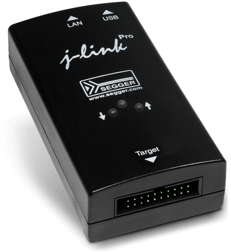
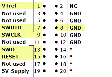
Connect any J-Link probe into the SWV interface of the target MCU. Then start the System View application on the host PC.
Convert ST-LINK to J-LINK
SEGGER offers a firmware upgrading the ST-LINK on-board on the Nucleo and Discovery Boards to a J-LINK On-Board debugger.
Start the System View for the first time, it will show a recorded example. Go to Tools → Preferences and uncheck the checkbox Load last data on start.
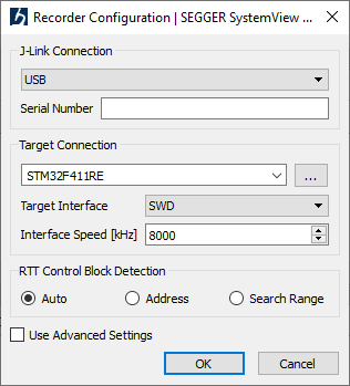
When starting to record a new session, it is recommended to check and set the target device. Press Alt + Return to show the device selection:
Press F5 or click on the start button to start recording. At the beginning step in this lab, the System View will display:
- Device information
- Messages of counter value
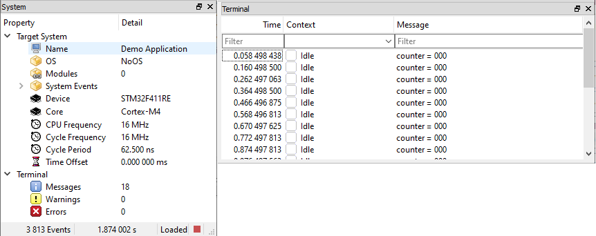
Record interrupts#
In the file stm32f4xx_it.c, in each concerning interrupt handler, add a pair of ISR recording function SEGGER_SYSVIEW_RecordEnterISR() and SEGGER_SYSVIEW_RecordExitISR() to track the interrupts. It automatically retrieves the interrupt ID via a special register implemented in the SEGGER_SYSVIEW_GET_INTERRUPT_ID() function macro:
void SysTick_Handler(void) {
  SEGGER_SYSVIEW_RecordEnterISR();
  HAL_IncTick();
  SEGGER_SYSVIEW_RecordExitISR();
}

void TIM1_UP_TIM10_IRQHandler(void) {
  SEGGER_SYSVIEW_RecordEnterISR();
  HAL_TIM_IRQHandler(&htim10);
  SEGGER_SYSVIEW_RecordExitISR();
}

void EXTI15_10_IRQHandler(void) {
  SEGGER_SYSVIEW_RecordEnterISR();
  HAL_GPIO_EXTI_IRQHandler(BUTTON_Pin);
  SEGGER_SYSVIEW_RecordExitISR();
}

void USART2_IRQHandler(void) {
  SEGGER_SYSVIEW_RecordEnterISR();
  HAL_UART_IRQHandler(&huart2);
  SEGGER_SYSVIEW_RecordExitISR();
}
This time, when recording with System View, there are many events captured. You will notice that between two log messages printed out, button interrupts are triggered twice.
Record functions#
The System View records to enter and the exit event of an interrupt, but it does not automatically record a user function. To do that, application must manually set the starting point of the function’s entry with one of:
SEGGER_SYSVIEW_RecordVoid(EventId), orSEGGER_SYSVIEW_RecordU32(EventId, Param), orSEGGER_SYSVIEW_RecordU32*(EventId, ...), orSEGGER_SYSVIEW_RecordString(EventId, char*)
and the ending point of that function with one of:
SEGGER_SYSVIEW_RecordEndCall(EventId), orSEGGER_SYSVIEW_RecordEndCallU32(EventId, Param)function.
These functions need an ID to distinguish the different APIs. ID is 2 bytes, comparing to an API function name which usually is much more than 2 bytes, it is very short to save sending bandwidth.
For example, to measure the main loop, and user callback functions, define some IDs starting from 32 as below:
#define APP_EVTID_MAIN_LOOP                       32
#define APP_EVTID_HAL_TIM_PeriodElapsedCallback   33
#define APP_EVTID_HAL_GPIO_EXTI_Callback          34
#define APP_EVTID_HAL_UART_TxCpltCallback         35
void HAL_TIM_PeriodElapsedCallback(TIM_HandleTypeDef *htim) {
  SEGGER_SYSVIEW_RecordU32(
      APP_EVTID_HAL_TIM_PeriodElapsedCallback,
      (U32)htim->Instance
  );
  if(htim == &htim10) {
    HAL_GPIO_TogglePin(LED_GPIO_Port, LED_Pin);
  }
  SEGGER_SYSVIEW_RecordEndCall(
      APP_EVTID_HAL_TIM_PeriodElapsedCallback
  );
}

void HAL_GPIO_EXTI_Callback(uint16_t GPIO_Pin) {
  SEGGER_SYSVIEW_RecordU32(
        APP_EVTID_HAL_GPIO_EXTI_Callback,
        (U32)GPIO_Pin
  );
  if(GPIO_Pin == GPIO_PIN_13) {
    counter++;
  }
  SEGGER_SYSVIEW_RecordEndCall(
      APP_EVTID_HAL_GPIO_EXTI_Callback
  );
}

void HAL_UART_TxCpltCallback(UART_HandleTypeDef *huart) {
  SEGGER_SYSVIEW_RecordVoid(APP_EVTID_HAL_UART_TxCpltCallback);
  if(huart == &huart2) {}
  SEGGER_SYSVIEW_RecordEndCall(APP_EVTID_HAL_UART_TxCpltCallback);
}

int main(void) {
    while (1) {
        SEGGER_SYSVIEW_RecordVoid(APP_EVTID_MAIN_LOOP);
        sprintf(buffer, "counter = %03d\r\n", counter);
        HAL_UART_Transmit(
            &huart1, (uint8_t*)buffer, strlen(buffer), HAL_MAX_DELAY
        );
        SEGGER_SYSVIEW_Print(buffer);
        HAL_Delay(100);
        SEGGER_SYSVIEW_RecordEndCall(APP_EVTID_MAIN_LOOP);
  }
}
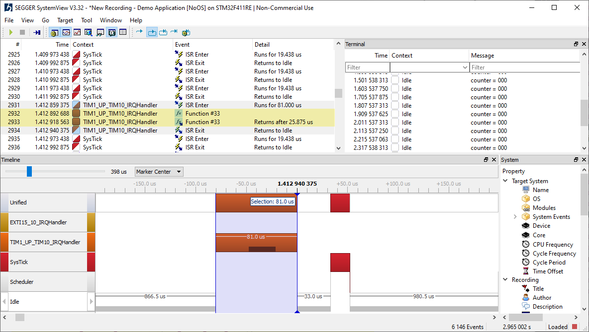
After this step, there are recorded events for starting and ending of a function. However, there is just event ID, not a human-friendly readable API name. In the below image, the TIM10 IRQ handler took 81 us to run, in which the user callback function with ID #33 took 25 us.
OS Description file#
In order for System View to properly decode API calls it requires a description file to be present in the C:\Program Files\SEGGER\SystemView\Description directory of System View. The name of the file has to be SYSVIEW_<OSName>.txt where <OSName> is the name as sent in the system description.
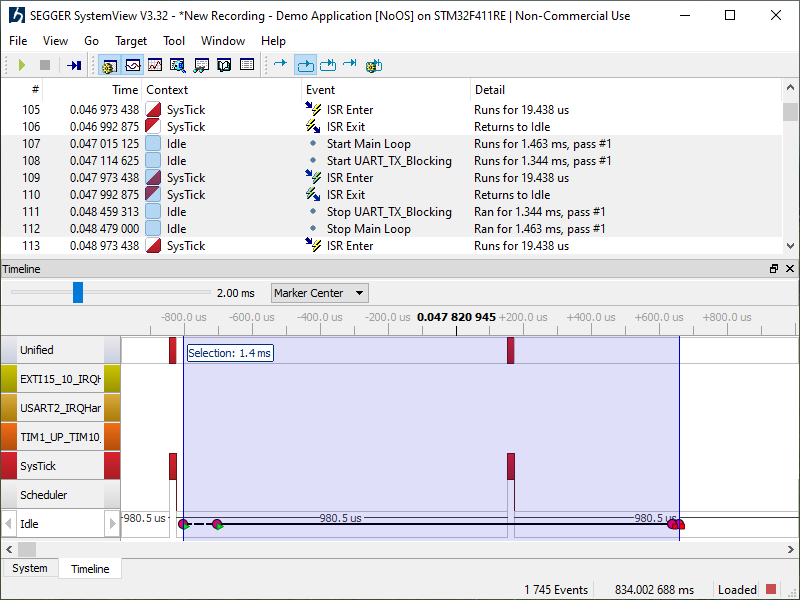
This lab use NoOS as the OS Name, therefore, it should be a SYSVIEW_NoOS.txt file in the description folder of System View. The user description folder is notified via System View log windows, e.g. C:\Users\<user>\AppData\Roaming\SEGGER.
OS Description syntax
A description file includes all API functions which can be recorded by the OS. Each line in the file is one function in the following format:
<ID> <Name> <Parameters> | <ReturnValue>
<Id> is the Id which is recorded for the API function. It can be in the range of 32 to 511.
<Name> is the name of the API function, displayed in the Event column of System View. It may not contain spaces.
<Parameters> and <ReturnValue> are the description string of the parameters which are recorded with the API functions. The ReturnValueDescription is optional.
The parameter display can be configured by a set of modifiers:
%b- Display parameter as binary.%B- Display parameter as hexadecimal string (e.g. 00 AA FF …).%d- Display parameter as signed decimal integer.%D- Display parameter as time value.%I- Display parameter as a resource name if the resource id is known to System View.%p- Display parameter as 4 byte hexadecimal integer (e.g. 0xAABBCCDD).%s- Display parameter as string.%t- Display parameter as a task name if the task id is known to System View.%u- Display parameter as unsigned decimal integer.%x- Display parameter as hexadecimal integer.
The following example shows a part of SYSVIEW_embOS.txt:
46 OS_CreateTask Task=%t Pri=%u Stack=%p Size=%u
In addition to the default modifiers the description file can define NamedTypes to map numerical values to strings, which can for example be useful to display the textual value of enums or error codes. The special character * represents for all remaining unmapped values.
NamedTypes have following format, can be used in the <Parameters> and the <ReturnValue>:
NamedType <TypeName> <Key>=<Value> [<Key1>=<Value1> ...]
The following example shows a part of SYSVIEW_embOS.txt:
# Types for parameter formatters
NamedType OSErr 0=OS_ERR_NONE 10000=OS_ERR_A

# API Functions
34 OSFunc Param=%OSFlag | Returns %OSErr
When a task pauses execution its state is recorded in the System View event.
This task state can be converted to a textual representation in System View with the TaskState description.
TaskState has following format:
TaskState <Mask> <Key>=<Value>, [<Key1>=<Value1>, ...]
For example:
# Task States
TaskState 0xFF 0=Ready, 1=Delayed or Timeout
Always have an empty line in the OS description file to make the last line is parsed properly
Write OS Description with Peripheral Info
We will define a lookup table for TIMx instance. The record function sends the address of the being called Timer:
SEGGER_SYSVIEW_RecordU32(
    APP_EVTID_HAL_TIM_PeriodElapsedCallback,
    (U32)htim->Instance
);
Therefore, we can map the received address value with the instance name. Use the Table 1. STM32F411xC/E register boundary addresses in Reference Manual document to know the addresses.
For the PIN number, we can need to call log2() function to get actual PIN in numeric order.
SEGGER_SYSVIEW_RecordU32(
    APP_EVTID_HAL_GPIO_EXTI_Callback,
    (U32)log2(GPIO_Pin)
);
Here is the sample OS Description for our project:
# Types
NamedType TIMx   *=%p 0x40010000=TIM1 0x40014400=TIM10
NamedType PINx   *=%u
NamedType UARTx  *=%p 0x40011000=USART1 0x40004400=USART2

# API IDs
32    Main_Loop
33    HAL_TIM_PeriodElapsedCallback   Instance = %TIMx
34    GPIO_EXTI_Callback              GPIO_Pin = %Pinx
35    HAL_UART_TxCpltCallback
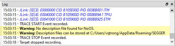
Re-run the System Viewer, you now can see the function name, with more detail as described in the OS Description file:
Measure performance#
To measure performance, System View uses Markers to calculate the execution time between a starting point and a corresponding ending point. The functions to measure performance is SEGGER_SYSVIEW_MarkStart() and SEGGER_SYSVIEW_MarkStop(), which need IDs to create pairs.
Define the Marker IDs:
#define APP_MARKER_MAIN_LOOP          0
#define APP_MARKER_UART_TX_BLOCKING   1
#define APP_MARKER_UART_TX_INTERRUPT  2
Then send the marker names in the Device Information callback function:
static void _cbSendSystemDesc(void) {
    SEGGER_SYSVIEW_SendSysDesc(...);

    SEGGER_SYSVIEW_NameMarker(
        APP_MARKER_MAIN_LOOP, "Main Loop"
    );
    SEGGER_SYSVIEW_NameMarker(
        APP_MARKER_UART_TX_BLOCKING, "UART_TX_Blocking"
    );
    SEGGER_SYSVIEW_NameMarker(
        APP_MARKER_UART_TX_INTERRUPT, "UART_TX_Interrupt"
    );
}
Compare Blocking and Non-Blocking Mode
We will call to 2 methods of sending characters on USART:
-
Blocking: function
HAL_UART_Transmit()put on byte on TX line and wait for it to be sent, the put another bytes. CPU is kept to busy while waiting. -
Non-Blocking: function
HAL_UART_Transmit_IT()set UART in interrupt mode: one byte is put on TX line the CPU does not wait for it to be sent, when a byte is sent, an interrupt is called to put next byte on TX again. CPU is free to run while a byte is being transmitted.
 while (1)
  {
    SEGGER_SYSVIEW_MarkStart(APP_MARKER_MAIN_LOOP);

    sprintf(buffer, "counter = %03d\r\n", counter);

#ifndef USE_UART_INTERRUPT
    // UART BLOCKING MODE
    SEGGER_SYSVIEW_MarkStart(APP_MARKER_UART_TX_BLOCKING);
    HAL_UART_Transmit(&huart2,
        (uint8_t*)buffer, strlen(buffer), HAL_MAX_DELAY
    );
    SEGGER_SYSVIEW_MarkStop(APP_MARKER_UART_TX_BLOCKING);
#else
    // UART INTERRUPT MODE
    SEGGER_SYSVIEW_MarkStart(APP_MARKER_UART_TX_INTERRUPT);
    HAL_UART_Transmit_IT(&huart2,
        (uint8_t*)buffer, strlen(buffer)
    );
#endif
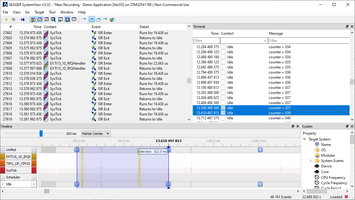
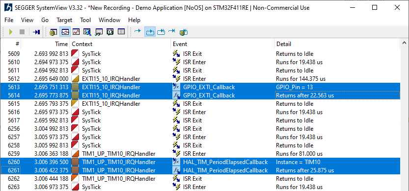
The result of measuring two performance points is as below:
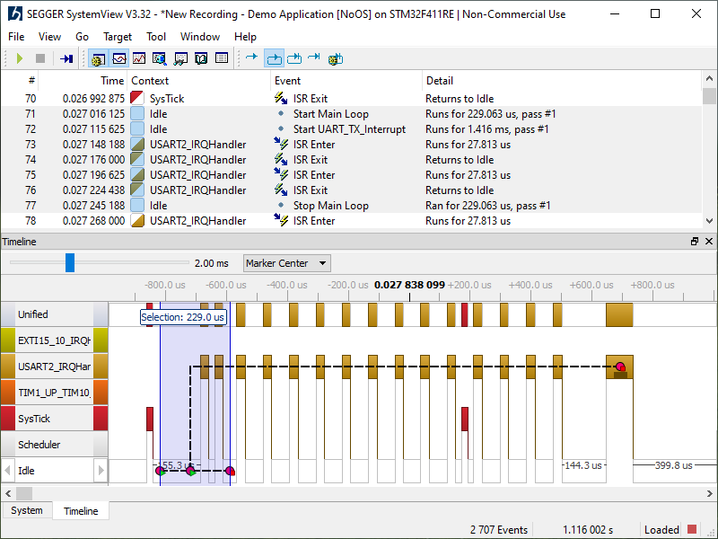
Look at the above images, it’s clear that in Non-Blocking case, the Main Loop has can finish a work faster as it can run while UART is transmitting a byte.
System View with No OS on Cortex-M0#
This section is a guide for F051R8 on STM32F0-DISCOVERY board.
#define SYSVIEW_APP_NAME        "Demo Application"
#define SYSVIEW_DEVICE_NAME     "STM32F051R8"
#define SYSVIEW_CORE_NAME       "Cortex-M0"
#define SYSVIEW_OS_NAME         "CM0-NoOS"

static void _cbSendSystemDesc(void) {
SEGGER_SYSVIEW_SendSysDesc("N="SYSVIEW_APP_NAME","
                            "D="SYSVIEW_DEVICE_NAME","
                            "C="SYSVIEW_CORE_NAME","
                            "O="SYSVIEW_OS_NAME);
SEGGER_SYSVIEW_SendSysDesc("I#15=SysTick");
}
For Cortex-M0, it is needed to increase the variable SEGGER_SYSVIEW_TickCnt in the SysTick interrupt, as soon as that handler is executed.
This variable is used in the function SEGGER_SYSVIEW_X_GetTimestamp() to correctly calculate the clock cycles.
void SysTick_Handler(void) {
    SEGGER_SYSVIEW_TickCnt++; // must be at the beginning
    SEGGER_SYSVIEW_RecordEnterISR();
    HAL_IncTick();
    SEGGER_SYSVIEW_RecordExitISR();
}
Done! Cortex-M0 now can provide precision timestamp for System View.
System View on RTOS#
Using an RTOS makes system analysis more complicated. However, System View is designed to work with RTOS after some simple steps.
Start a new project#
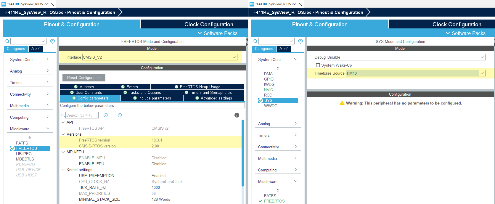
Let’s create a new project using FreeRTOS V10.3.1 using CMSIS-RTOS V2.
Note: RTOS should use SysTick for its own OS delay function, while HAL function also needs a time-base to operate its own polling delay method.
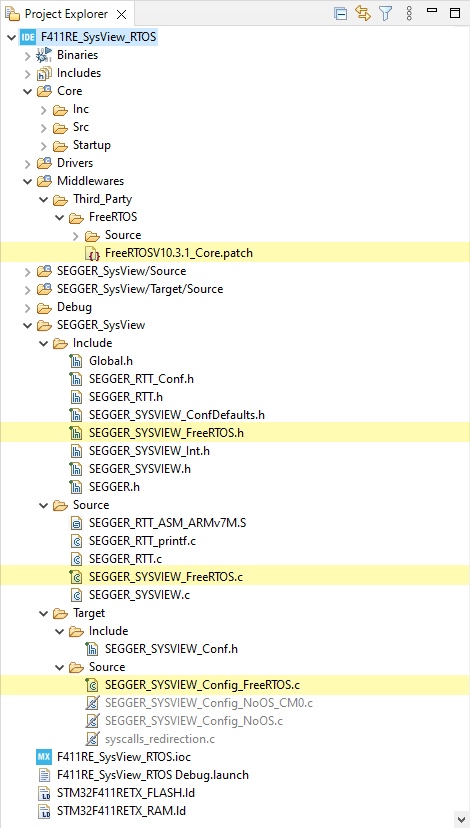
Import System View files#
The core files of Segger System View is the same as they are used in the Non-OS firmware.
The difference is the config files for RTOS, which are found in the target FreeRTOS version or any other RTOS such as embOS.
FreeRTOSV10
│
│   SEGGER_SYSVIEW_FreeRTOS.c
│   SEGGER_SYSVIEW_FreeRTOS.h
│
├───Config
│   └───Cortex-M
│           SEGGER_SYSVIEW_Config_FreeRTOS.c
│
└───Patch
        FreeRTOSV10_Amazon_Core.patch
        FreeRTOSV10_Core.patch
Copy all of those files to the project.
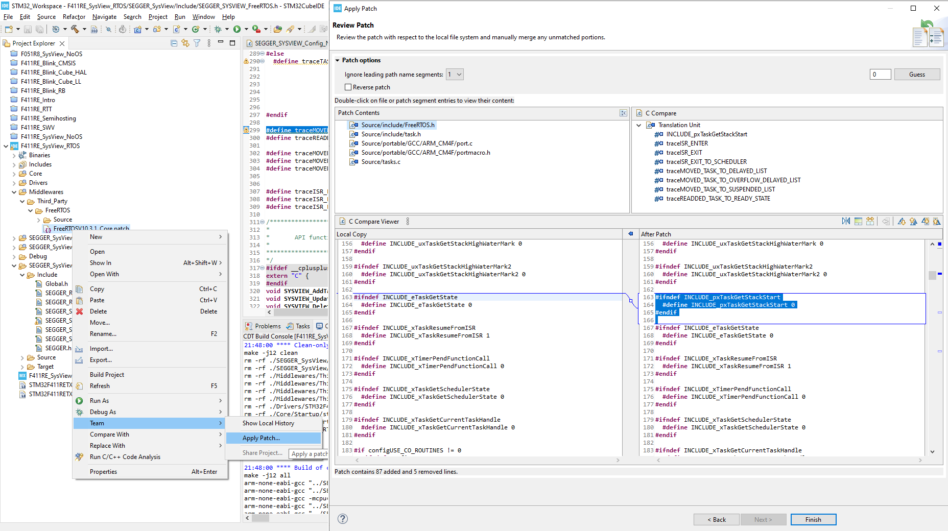
Apply patch#
The patch file may not be applied for newer FreeRTOS version, such as V10.3+.
It easy to modify the patch to apply into a newer version, or download FreeRTOSV10.3.1_Core.patch.
Configure System View#
-
Include
SEGGER_SYSVIEW_FreeRTOS.hat the end of the fileFreeRTOSConfig.hto override some RTOS definitions of tracing functions. -
Finally, configure System View in the file
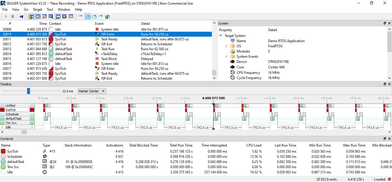
SEGGER_SYSVIEW_Config_FreeRTOS.cwhich sends System Information, Interrupt ID & Name, Timers and Markers.#define SYSVIEW_APP_NAME "Demo RTOS Application" #define SYSVIEW_DEVICE_NAME "STM32F411RE" #define SYSVIEW_CORE_NAME "Cortex-M4" #define SYSVIEW_OS_NAME "FreeRTOS" #define SYSVIEW_RAM_BASE (0x20000000) static void _cbSendSystemDesc(void) { SEGGER_SYSVIEW_SendSysDesc("N="SYSVIEW_APP_NAME"," "D="SYSVIEW_DEVICE_NAME"," "C="SYSVIEW_CORE_NAME"," "O="SYSVIEW_OS_NAME); SEGGER_SYSVIEW_SendSysDesc("I#15=SysTick"); } -
Include SEGGER’s headers and call to
SEGGER_SYSVIEW_Conf()to initialize System View:#include "SEGGER_SYSVIEW_Conf.h" #include "SEGGER_SYSVIEW.h" int main() { SEGGER_SYSVIEW_Conf(); ... }
Run System View#
Done! You can build and run System Viewer to see RTOS running with a Default Task and a Timer Service.