GCC Inline Assembly code
The asm keyword allows you to embed assembler instructions within C code. GCC provides two forms of inline asm statements. A basic assembly statement is one with no operands, and an Extended assembly statement which includes one or more operands to interact with C variables.
Last update: 2022-06-04
Table of Content
STM32-Tutorials F411RE_Assembly.zip
Assembly Extension#
GCC defines Inline Assembly as an extension for C, read more at Using Assembly Language with C.
Using Extended Assembly typically produces smaller, safer, and more efficient code, and in most cases it is a better solution than Basic Assembly. However, there are two situations where only Basic Assembly can be used:
-
Extended Assembly statements have to be inside a C function, so to write inline assembly language at file scope (“top-level”), outside C functions, you must use Basic Assembly.
You can use this technique to emit assembler directives, define assembly language macros that can be invoked elsewhere in the file, or write entire functions in assembly language. Basic Assembly statements outside of functions may not use any qualifiers.
-
Functions declared with the naked attribute also require Basic Assembly.
Code optimization
Do not expect a sequence of assembly statements to remain perfectly consecutive after compilation. If certain instructions need to remain consecutive in the output, put them in a single multi-instruction assembly statement. Note that GCC’s optimizers can move assembly statements relative to other code, including across jumps.
Under certain circumstances, GCC may duplicate (or remove duplicates of) your assembly code when optimizing. This can lead to unexpected duplicate symbol errors during compilation if your assembly code defines symbols or labels.
Assembly Instruction Set documentation
It’s recommended to read the document for a specific Cortex-M line.
This guide is written based on STM32F411RE MCU, which has a Cortex-M4 microprocessors. The document is PM0214: STM32 Cortex®-M4 MCUs and MPUs programming manual.
Basic Assembly#
Refer to the “Instruction Set” section in Programming Manual document to get details of all instructions.
Take an example:
MOV R0, R1      ; Copy value in R1 to R0
ADD R0, #12     ; Add 12 to value of R0 and save the sum to R0
Inline assembly code is used to write pure assembly code in a C/C++ program:
int main() {
    __asm volatile("MOV R0, R1");
    __asm volatile("ADD R0, R1");
}
Use in block of instructions, note the \n\t at the end of each instruction:
__asm volatile(
    "MOV R0, R1\n\t"
    "ADD R0, R1\n\t"
    );
Example#
We will write a simple code to:
- Load values from 2 addresses
0x20001000and0x20001004 - Store the sum of those numbers to a new address
0x20001008
Inline Assembly ode:
int main(void) {
  __asm volatile(
    "LDR R1, =#0x20001000\n\t" /* Load address 0x20001000 to R1 */
    "LDR R2, =#0x20001004\n\t" /* Load address 0x20001004 to R2 */
    "LDR R3, =#0x20001008\n\t" /* Load address 0x20001008 to R3 */
    "LDR R0, [R1]\n\t"         /* Load data at the address pointing by R1, save to R0 */
    "LDR R1, [R2]\n\t"         /* Load data at the address pointing by R2, save to R1 */
    "ADD R0, R1\n\t"           /* Add R0 to R1, save to R0 */
    "STR R0, [R3]\n\t"         /* Store R0 to the address pointing by R3 */
  );
}
Check the list file to see that the assembler will produce below instructions:
; __asm volatile(
      ; "LDR R1, =#0x20001000\n\t"
 800010c:   4903        ldr r1, [pc, #12]   ; (800011c <main+0x14>)
      ; "LDR R2, =#0x20001004\n\t"
 800010e:   4a04        ldr r2, [pc, #16]   ; (8000120 <main+0x18>)
      ; "LDR R3, =#0x20001008\n\t"
 8000110:   4b04        ldr r3, [pc, #16]   ; (8000124 <main+0x1c>)
      ; "LDR R0, [R1]\n\t"
 8000112:   6808        ldr r0, [r1, #0]
      ; "LDR R1, [R2]\n\t"
 8000114:   6811        ldr r1, [r2, #0]
      ; "ADD R0, R1\n\t"
 8000116:   1840        adds    r0, r0, r1
      ; "STR R0, [R3]\n\t"
 8000118:   6018        str r0, [r3, #0]
      ; );
; /* Loop forever */
      ; for(;;);
 800011a:   e7fe        b.n 800011a <main+0x12>
 800011c:   20001000    .word   0x20001000
 8000120:   20001004    .word   0x20001004
 8000124:   20001008    .word   0x20001008
You can generate list file using
objdump:arm-none-eabi-objdump -h -S app.elf > app.list
You will notice that, the immediate 32-bit number 0x20001000 can not be encoded into 16-bit Thumb instruction, the assembler stores the constant in the text segment close to the referencing instruction and then references the value using (usually) PC-relative addressing, i.e. some offset from PC register.
The number 0x20001000 is stored at address 0x0800011c.
When CPU executes the instruction at 0x800010c, it will execute:
800010c: 4903 ldr r1, [pc, #12] ; (800011c <main+0x14>)
The value of PC is the current instruction, mentioned in document PM0214, section 2.1.3 Core registers, which is 0x800010c. The offset is 12 which is 0xC You will do a calculation 0x0800010c + 0xC = 0x08000118 and found out the target address is not 0x800010c!!! Why???
Let check the LDR instruction in PM0214, section 3.4.5 LDR, PC-relative, and section 3.3.6 PC-relative expressions:
PC-relative expressions
A PC-relative expression or label is a symbol that represents the address of an instruction or literal data. It is represented in the instruction as the PC value plus or minus a numeric offset. The assembler calculates the required value from the label and the address of the current instruction. If the offset is too big, the assembler produces an error.
- For the
B,BL,CBNZ, andCBZinstructions, the value of the PC is the address of the current instruction plus four bytes. (2 instructions)- For all other instructions that use labels, the value of the PC is the address of the current instruction plus four bytes, with bit[1] of the result cleared to 0 to make it word aligned.
- Your assembler might permit other syntaxes for PC-relative expressions, such as a label plus or minus a number, or an expression of the form
[PC, #number].
Our case is LDR instruction:
- the PC value is now
0x0800010c + 0x4 = 0x08000110, bit[1] is already0, so the final PC based address is0x08000110 - the target address to be read is
0x08000110 + 0xC = 0x0800011Cwhich is correct address storing the number0x20001000
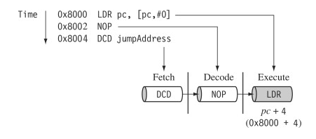
Actual PC value is ahead of the executing instruction!
Refer to ARM processor Pipeline.
The Cortex-M4 processor is built on a high-performance processor core, with a 3-stage pipeline Harvard architecture.
In the execute stage, the PC always points to the address of the instruction plus 4 bytes (in Thumb state). In other words, the pc always points to the address of the instruction being executed plus two instructions ahead.
This is important when the PC is used for calculating a relative offset and is an architectural characteristic across all the pipelines. Note when the processor is in ARM state the PC is the instruction address plus 8.
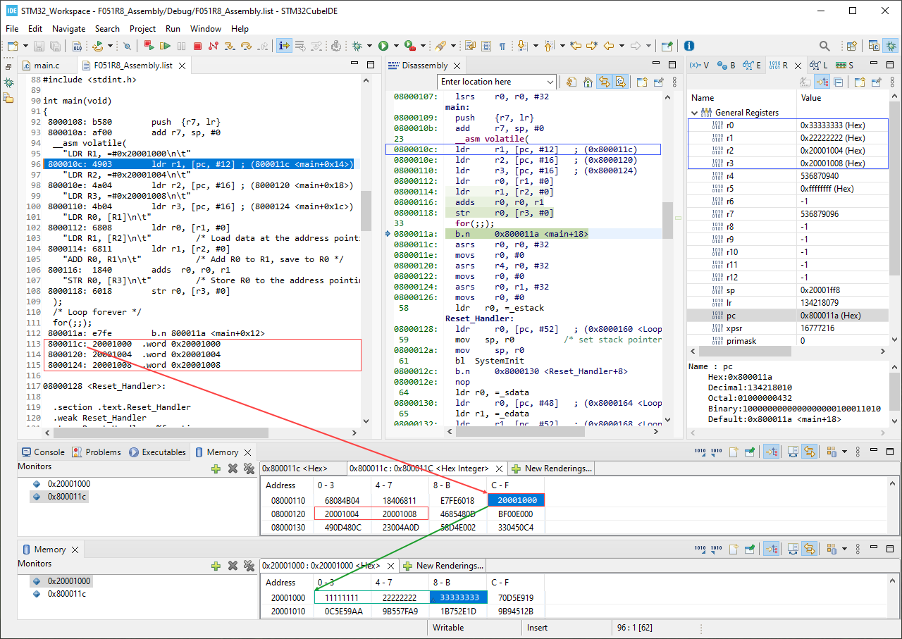
Compile and run the example code in the Debug mode, you can see how data is loaded into registers and memory address. Open Memory Browser to see and edit data in memory space.
Extended Assembly#
The GCC Inline Assembly full syntax is:
__asm volatile (
    AssemblerTemplate
    : OutputOperands
    [: InputOperands
    [: Clobbers ]])
-
AssemblerTemplate: This is a literal string that is the template for the assembler code. It is a combination of fixed text and tokens that refer to the input, output, and goto parameters.
-
OutputOperands: A comma-separated list of the C variables modified by the instructions in the AssemblerTemplate. An empty list is permitted.
-
InputOperands: A comma-separated list of C expressions read by the instructions in the AssemblerTemplate. An empty list is permitted.
-
Clobbers: A comma-separated list of registers or other values changed by the AssemblerTemplate, beyond those listed as outputs. An empty list is permitted.
This is useful for below cases:
- Move the content of
Cvariable to an ARM register - Move the content of an ARM register to a C variable
- Access assembly instructions that are not readily available to C programs
Examples#
No extra operand:
__asm volatile("MOV R0, R1");    // is the same as
__asm volatile("MOV R0, R1":::);
With input operand:
int val = 50;
__asm volatile("MOV R0, %0": : "r"(val)); // R0 = 50
__asm volatile("MOV R1, %0": : "i"(50));  // R1 = 50
movs    r3, #50 ; 0x32
mov     r0, r3  ; R0 = R3 = 0x32
movs    r1, #50 ; 0x32
in which:
-
No output operand
-
Input operand is
"r"(val)using constraintrmeaning Register operand.
Input operand is"i"(50)using constraintimeaning Immediate value.Refer to GCC ASM Contraints
-
%0is the first place-holder, which will be replaced byvalinput
With output operand:
int control_reg;
__asm volatile("MRS %0, CONTROL": "=r"(control_reg)); // control_reg = CONTROL
mrs r3, CONTROL     ; R3 = CONTROL
str r3, [r7, #0]    ; store R3 to control_reg at R7+0
With both input and output operand:
int var1=10;
int var2;
__asm volatile("MOV %0, %1": "=r"(var2): "r"(var1)); // var2 = var1
ldr     r3, [r7, #4]    ; load R3 from var1 at R7+4
str     r3, [r7, #0]    ; store R3 to var2 at R7+0
other example:
int p1, *p2;
p2 = (int*) 0x20000000;
__asm volatile("LDR %0, [%1]": "=r"(p1) : "r"(p2)); // pi = *p2
ldr r3, [r7, #4]    ; load R3 from p2 at R7 + 4, its value is an address
ldr r3, [r3, #0]    ; dereference R3, to get value stored at that address
str r3, [r7, #0]    ; store value in R3 to p1 at R7+0
Registers for Local Variables#
You can define a local register variable and associate it with a specified register like this:
register int *foo __asm ("r12"); // foo is R12 register
*foo = 12;
mov  r3, ip          ; copy value of R12 (IP) register to R3
movs r2, #12         ; save 12 to R2
str  r2, [r3, #0]    ; store value in R2 to the address saved in R3 (=R12)
The register keyword is required, and cannot be combined with static. The register name must be a valid register name for the target platform.
Do not use type qualifiers such as const and volatile, as the outcome may be contrary to expectations. In particular, using the volatile qualifier does not fully prevent the compiler from optimizing accesses to the register.
Change the access level#
As mentioned in Access Levels, the application runs in the Privileged level by default. However, you can change the access mode to Unprivileged level.
The CONTROL register has the bit[0] nPRIV to change the access level. To change the CONTROL register, you have to use MRS and MSR assembly instructions.
When application enters the Unprivileged level, application is restricted to use the MSR and MRS instructions, therefore, it can not change the CONTROL register.
The application must use the SVC instruction to make a supervisor call to transfer control to privileged software. The SVC instruction has a number embedded within it, often referred to as the SVC number. On most ARM processors, this is used to indicate the service that is being requested. On microcontroller profiles, the processor saves the argument registers to the stack on the initial exception entry.
The startup file startup_stm32f411retx.s has defined an SVC_Handler() function, so we can override that function to get our code run in privileged level:
Example#
void SVC_Handler(void) // reduced handler which ignores SVC number param
{
    // Move back to Privileged level
    __asm volatile(
        "MRS R0, CONTROL\n\t"   ; Copy CONTROL to R0
        "BIC R0, R0, #1\n\t"    ; Clear bit 0 in R0
        "MSR CONTROL, r0"       ; Store R0 to CONTROL
    );
}

int main(void) {
    // Move to Unprivileged level
    __asm volatile(
        "MRS R0, CONTROL\n\t"
        "ORR R0, R0, #1\n\t"    ; Set bit 0 in R0
        "MSR CONTROL, r0"
    );

    // Call SVC 0 to rise an interrupt
    __asm volatile("SVC #0")
}